Honeywell TH8321WF1001 Installation⁚ A Comprehensive Guide
This guide provides a detailed walkthrough for installing the Honeywell TH8321WF1001 Wi-Fi thermostat․ Following the step-by-step instructions will ensure proper installation and device configuration, including setting installer options and connecting to a Wi-Fi network․ This is the first step for setting up a new thermostat․
Getting Started with Your TH8321WF1001
Before initiating the installation of your Honeywell TH8321WF1001 thermostat, it’s crucial to gather all necessary tools and materials․ This includes a Phillips head screwdriver, a small flathead screwdriver, and the provided screws and wall anchors․ Ensure your home’s power is turned off at the circuit breaker to prevent electrical shock during the wiring process․ Carefully unpack the thermostat and verify that all components are present․ This includes the thermostat unit itself, the wallplate, and the installation guide․ Familiarize yourself with the basic structure of the thermostat․ Understand the location of the power button and the menu options․ It’s also beneficial to locate the terminal connections on the back of the thermostat․ A solid understanding of these components will aid in the installation process․ Review the installation guide thoroughly before beginning, paying close attention to the safety warnings and wiring diagrams․ Note the date code and other identification information printed on the device, as it may be needed for later setup or troubleshooting․ Proper preparation is key for a smooth and efficient installation process, ensuring the correct functionality of your new thermostat․
Separating the Thermostat from the Wallplate
The initial step in the physical installation process involves separating the Honeywell TH8321WF1001 thermostat from its wallplate․ This is a necessary step to access the mounting points and wiring terminals located on the wallplate․ Begin by locating the small release button, typically situated on the top or bottom of the thermostat unit․ Once located, firmly press this button․ While holding the release button, gently pull the thermostat body away from the wallplate․ It should detach relatively easily without excessive force․ If resistance is felt, double-check that the button is fully depressed․ Avoid any forceful pulling, as this could damage the thermostat or wallplate components․ Once separated, set the thermostat body aside in a safe location, away from any potential hazards․ The wallplate should now be securely attached to the wall․ It will have exposed terminals and mounting screw holes․ Take note of the orientation of the wallplate․ This will be helpful when reattaching the thermostat later․ This separation process is crucial for the next steps involving mounting and wiring․ The proper detachment will ensure the ease of installation and prevent damage to the unit․
Mounting the Wallplate Securely
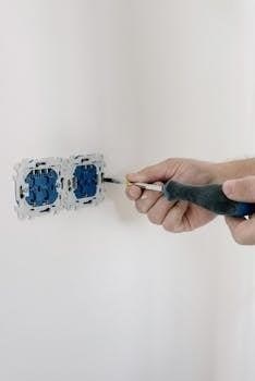
With the thermostat detached, the next step involves securely mounting the wallplate to the wall․ Begin by positioning the wallplate against the wall, ensuring it’s level and oriented correctly, as noted during the separation process․ The wallplate should align with the existing hole where the old thermostat was placed․ If you are installing in a new location, you’ll need to mark the screw hole locations․ Use a pencil to mark the positions on the wall, using the wallplate as a template․ Then, remove the wallplate and prepare the holes for mounting screws․ For drywall, use a 3/16-inch drill bit to make the pilot holes․ If the wall is plaster, you will need to use a 7/32-inch drill bit․ If you are using anchors, insert them into the holes․ Now, position the wallplate back onto the wall, aligning it with the holes․ Use the provided screws to secure the wallplate to the wall․ Make sure the wallplate is firmly attached and doesn’t wobble․ Do not overtighten the screws, as this can damage the wallplate or the wall itself․ The wallplate should sit flush against the wall after installation, providing a solid base for the thermostat․
Connecting Power to the Thermostat
Once the wallplate is securely mounted, the next crucial step involves connecting the power supply to the thermostat․ The Honeywell TH8321WF1001 requires a 24VAC power source for operation․ This is a common voltage for heating and cooling systems․ To begin, identify the common wire from the secondary side of your cooling transformer․ This wire must be connected to the designated “C” terminal on the thermostat’s wallplate․ The “C” terminal is essential for providing continuous power to the thermostat, especially when running on Wi-Fi․ For systems with two transformers (one for heating and one for cooling), the common wire from the cooling transformer must be used․ Ensure the power to the heating and cooling system is turned off at the breaker before proceeding with any wiring tasks to prevent electrical shock․ If you are not comfortable working with electrical wiring, it’s best to seek assistance from a professional HVAC technician to avoid any accidents and ensure the wiring is done correctly․ Improper wiring can damage the thermostat or the HVAC system․ Carefully connect the appropriate wires to the corresponding terminals, ensuring they are secure․ After wiring, double-check to make sure that all connections are correct․

Understanding Terminal Designations
Understanding the terminal designations on the Honeywell TH8321WF1001 is crucial for proper wiring and system operation․ These terminals facilitate communication between the thermostat and your heating, ventilation, and air conditioning (HVAC) system․ For conventional systems, common terminals include “R” for heating power, “Rc” for cooling power, “W” for heating relay, “Y” for compressor contactor, and “G” for fan relay․ Additionally, there’s the “C” terminal for the common wire from the secondary side of the cooling transformer, which is essential for powering the thermostat․ For heat pump systems, you’ll find terminals like “O” or “B” for the changeover valve, which determines whether the system is in heating or cooling mode․ Some heat pump systems may have an “Aux” or “E” terminal for auxiliary heat stages․ The “R” and “Rc” terminals are often joined by a jumper for single-transformer systems․ Note that some terminals may not be used depending on your system type․ Carefully refer to the installation manual to ensure that the correct wires are connected to the designated terminals to prevent damage or malfunction․ It is very important to double-check each wire connections after they are made․

Performing Installer Setup⁚ Key Options
The installer setup on the Honeywell TH8321WF1001 allows for customized configuration to suit your specific HVAC system and preferences․ Accessing this menu is usually done through the thermostat’s menu options, often requiring a password, which is typically the date code found on the back of the unit plus 1234․ Key setup options include selecting the application type, either residential or commercial․ You’ll also need to configure your system type, such as a conventional system (furnace and air conditioner) or a heat pump system, and if it has one or two transformers․ Other options include the number of heating and cooling stages, whether you have auxiliary heat, and the type of fan control․ Additionally, you can configure display preferences, such as temperature units (Fahrenheit or Celsius) and backlight settings․ These installer setup options determine how the thermostat will control your HVAC system and display information․ It’s important to make sure that the settings are accurate for your particular setup to ensure efficient and correct operation of your device․ Make sure to follow each step carefully when changing settings․
Wiring Guide for Conventional Systems
When wiring the Honeywell TH8321WF1001 for a conventional system, it’s crucial to understand the terminal designations․ For a standard 1-heat/1-cool system with one transformer, connect the heating wire to the ‘R’ terminal, the cooling wire to the ‘Y’ terminal, and the fan wire to ‘G’․ If using a two-transformer system, you might have separate ‘Rc’ and ‘Rh’ terminals; connect the cooling transformer to ‘Rc’ and the heating transformer to ‘Rh’․ The common wire from the transformer should go to the ‘C’ terminal․ For a system with two transformers, you’ll likely need to remove a jumper wire, if present, between ‘Rc’ and ‘Rh’․ Ensure all connections are secure and wires are properly inserted into the terminals․ An optional outdoor or remote sensor can be connected to the appropriate terminals if available; Always double-check the wiring diagram included with your specific system to ensure compatibility and proper functionality of your system․ Incorrect wiring can lead to system damage or malfunction, so please be careful․ Always turn the power off when doing any electrical work․
Wiring Guide for Heat Pump Systems
For heat pump systems, the Honeywell TH8321WF1001 requires a slightly different wiring approach․ In a basic 1-heat/1-cool heat pump setup without auxiliary heat, the compressor wire connects to the ‘Y’ terminal․ The changeover valve wire, which determines whether the system is in heating or cooling mode, should be connected to the ‘O/B’ terminal, depending on the specific heat pump configuration, ‘O’ for cooling and ‘B’ for heating․ The fan wire goes to ‘G’․ The common wire from the transformer connects to the ‘C’ terminal․ In a 2-heat/2-cool heat pump system, you may have additional wires for second-stage heating and cooling, which should be connected to ‘W2’ and ‘Y2’ terminals, respectively․ It’s important to consult the specific heat pump system’s manual to determine the proper connections as heat pump wiring can vary․ Always make sure to remove any jumpers that are not required for your particular heat pump system․ If using a two-transformer system, you will probably need to make sure the ‘Rc’ and ‘Rh’ terminals are connected correctly․ Double check for correct wiring․
Connecting the Thermostat to Wi-Fi
After completing the installer setup, the Honeywell TH8321WF1001 will prompt you to connect to a Wi-Fi network․ Select ‘Yes’ to proceed with the connection․ The thermostat will then display available Wi-Fi networks․ Choose your network from the list and enter the network password using the touchscreen interface․ Once you successfully enter the password, the thermostat will attempt to connect to the network․ If successful, it will display a confirmation message, and the Wi-Fi icon will appear on the main screen․ If the connection fails, the thermostat will show a ‘Connection Failed’ message, prompting you to review your network settings and password․ The homeowner must also have a Total Connect Comfort account for full access to remote control features․ The Thermostat MAC and CRC will be needed during registration․ This process enables remote control and monitoring capabilities․ If you select ‘No,’ the homeowner can connect to the Wi-Fi network later․ You can also connect to a hidden network․

Troubleshooting Wi-Fi Connection Issues
If the Honeywell TH8321WF1001 fails to connect to your Wi-Fi network, a ‘Connection Failed’ screen will appear․ This screen often provides specific reasons for the failure, prompting you to investigate further․ Verify that the Wi-Fi network name and password have been entered correctly․ Double-check for typos and ensure that the case (upper or lower) matches your Wi-Fi password․ If your Wi-Fi network name is hidden, you will need to manually enter it via the Wi-Fi setup menu․ Also, confirm that your wireless router is functioning properly․ A weak signal can cause a connection failure, so consider moving the router closer to the thermostat or use a Wi-Fi extender․ Additionally, ensure that your Wi-Fi network is compatible with the thermostat, which supports 802․11 B/G/N home wireless routers using the 2․4 GHz frequency․ If the problem persists, try restarting both your router and the thermostat․ If you continue experiencing issues, refer to the user manual or contact Honeywell support for further guidance․
